In the industrial automation control, the pneumatic control valve sometimes needs fault location, the following puts forward two methods of double acting pneumatic control valve fault location, for your reference.
1. The scheme is mainly composed of pneumatic control valve, solenoid valve, positioner, retaining valve, one-way valve, diaphragm pump pressure reducing valve, air storage tank, etc. Its working principle is as follows:
When the air source of the control system fails (losing gas), the position retaining valve (whose action mode is opposite to the retaining valve) will automatically open, and the control air source of the solenoid valve will be cancelled, and the slide valve of the solenoid valve will be reset under the action of the spring. One of the two solenoid valves will exhaust and the other will be inlet, and the one-way valve will be closed. The air supply will be supplied to the valve by the air source stored in the air storage tank, so as to realize the full closing or full closing of the valve Yes. The conversion of full close or full open can be realized by adjusting the connection mode of pneumatic directional valve.
If the valve is to be kept in place, the pneumatic valve should be installed and the pipeline connection should be changed. The self-locking valve can be used to directly control the retaining valve, solenoid valve, one-way valve and air tank.
2. In order to ensure that the valve has several actions when the gas source is cut off, the following scheme can be adopted for the control valve.
The scheme is composed of air tank, one-way valve, locking valve and stop valve. Its working principle is as follows:
In case of air source failure (loss of gas), the one-way valve is closed and the locking valve is out of gas. Under the action of spring, the slide valve of the locking valve is reset and the air circuit is reversed. The air source pipeline of the system is disconnected, and the pipeline of the air storage tank is connected. The gas reservoir supplies air to the valve to ensure that the valve has several actions and realize the purpose of continuous control. Due to the limited capacity of the air tank, and the pressure of the air source in the air tank decreases with the action of the valve, it is not allowed to use the gas tank for a long time to supply gas to the valve. The capacity of the gas storage tank used in this scheme should be larger than that of the general protective gas tank. When the gas source is cut off, the number of valve actions is related to the capacity of the air tank.
As for the retaining scheme of pneumatic diaphragm control valve, there is another reference: the pneumatic control valve is connected in series between the positioner and the actuator and one of the two position three-way solenoid valve. The retaining valve is used to maintain the position when the air is cut off, and the solenoid valve is used to maintain the position when the signal is off. However, the electro-magnetic valve must be interlocked with the positioner (set in the control program), that is, the positioner has a signal, and the electric valve is electrically controlled The magnetic valve must be electrified. Once the positioner loses the signal, the solenoid valve must be cut off immediately.

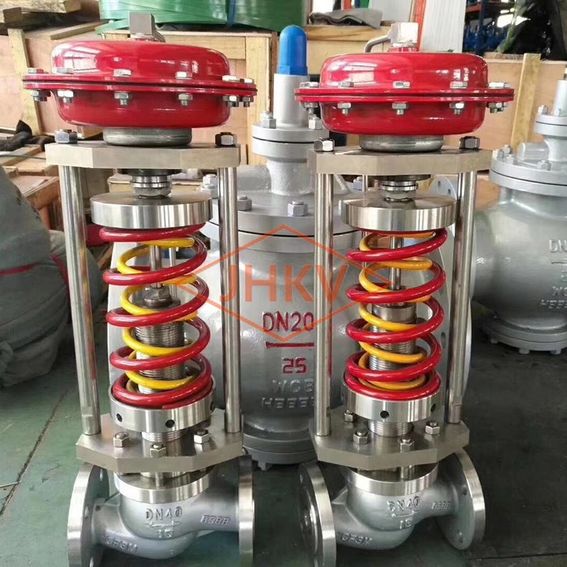 Self-actuated regulator
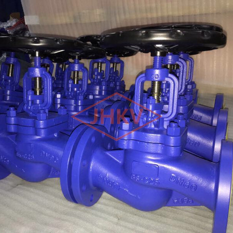 DIN Globe Valve
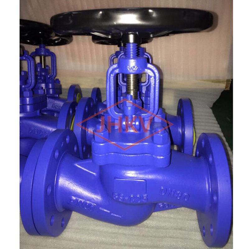 DIN Globe Valve
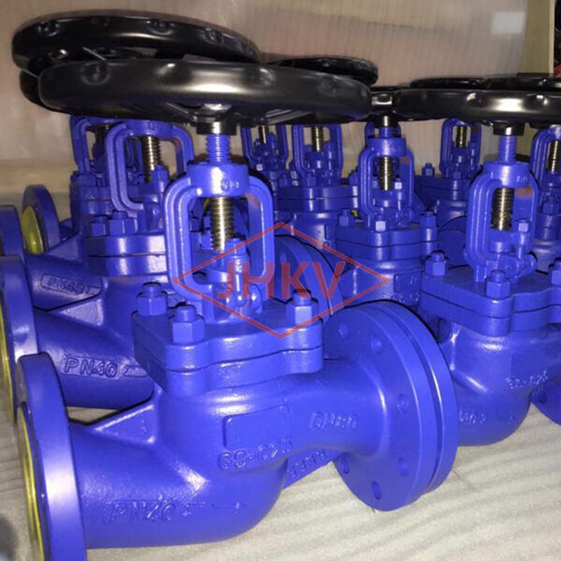 DIN Globe Valve
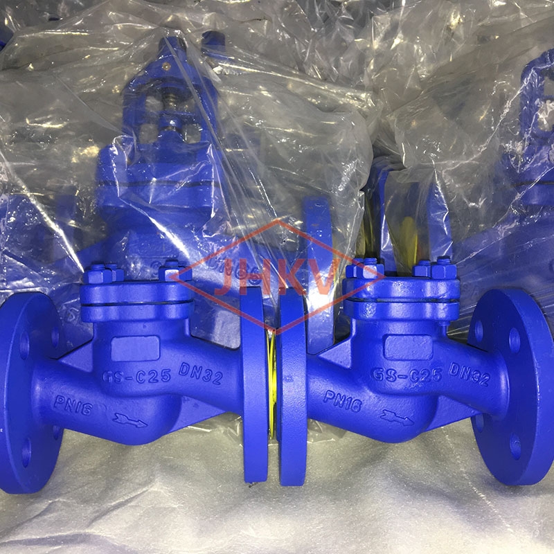 DIN CHECK VALVE
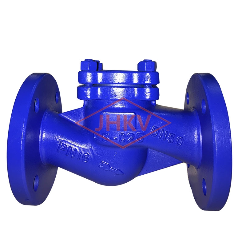 DIN CHECK VALVE
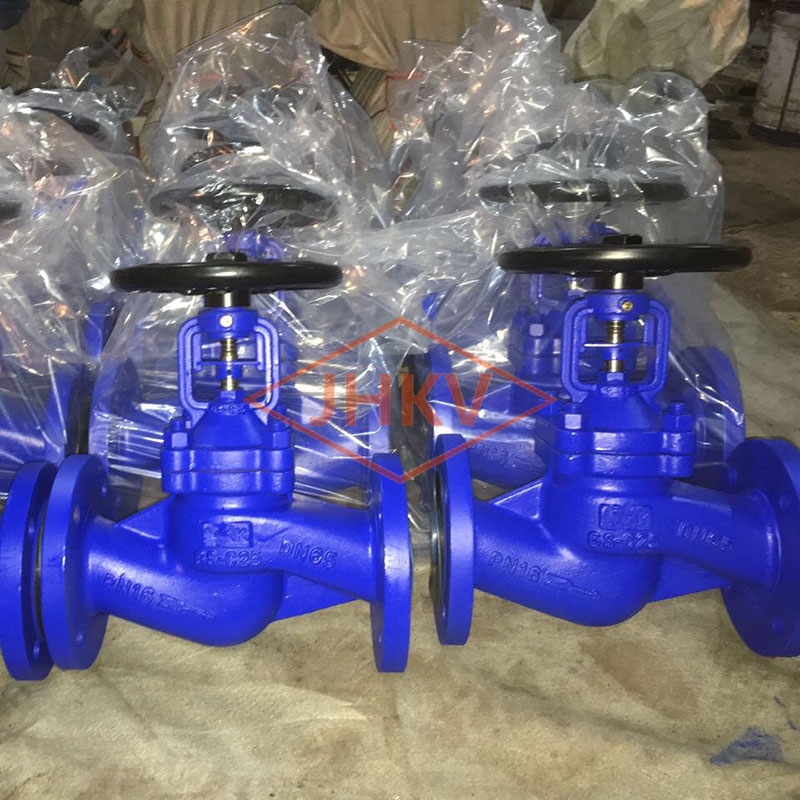 DIN Bellows Globe Valve
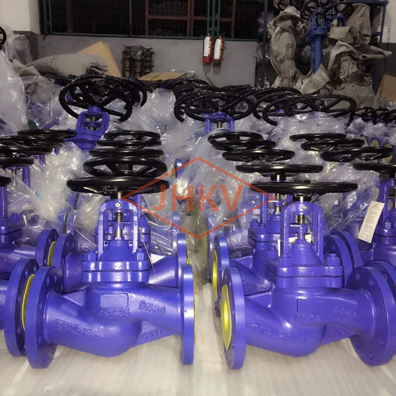 DIN Bellows Globe Valve
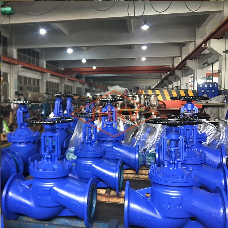 DIN Bellows Globe Valve
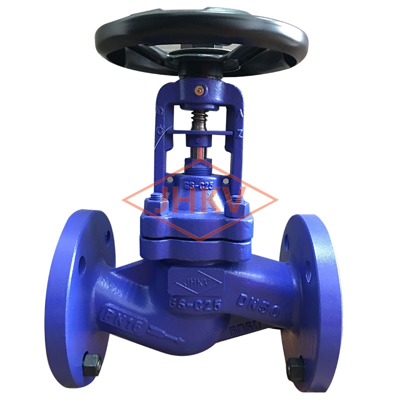 DIN Bellows Globe Valve